Knock means knock (knock … knock) Knock sensor means knock sensor, as the name suggests, its job is to identify knocks to the car engine and announce them to the ECU. These blows are caused by the piston, connecting rod and moving parts due to incomplete fuel and bad ignition (early or late) to the car engine (incomplete explosion causes this process) and in the long run it will cause engine damage and wear. became. In this section of Act Group, on the subject of “What is an impact sensor in a car and what are its uses?” we pay.
It also increases the sound of the engine and the vibration of the engine increases and as a result the life of the engine decreases.

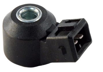
Figure 1
Impact sensor
The impact sensor on the engine body is mostly found in the peak stress areas. Generally, there is one impact sensor in the car, but in some advanced engines, several impact sensors are used in different parts of the engine.
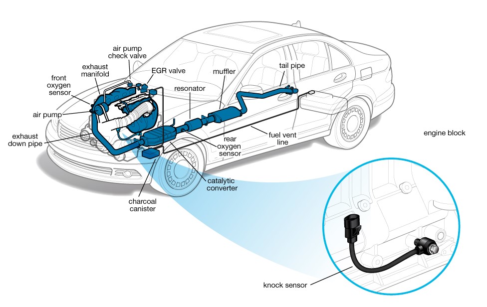
Figure 2
Is closed in the engine block on the side of the air manifold and between cylinders 2 and 3 . In advanced new cars, an impact sensor is used for every two cylinders or every cylinder (in order to control, advance and retard each cylinder separately and make the engine work smoothly)
The effects of failure of the sensor
1- If this sensor fails due to wrong information reaching the ECU , the engine will work with vibration.
2- Due to the confusion of the correct ignition timing and spark advance change, the engine temperature rises.
3- Failure of the impact sensor causes a slight increase in fuel consumption.
4- If this sensor fails, the check light will turn on.
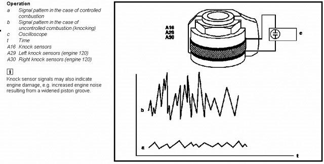
Figure 3: Impact sensor generates a voltage signal at its output due to vibration and generally has two pins.
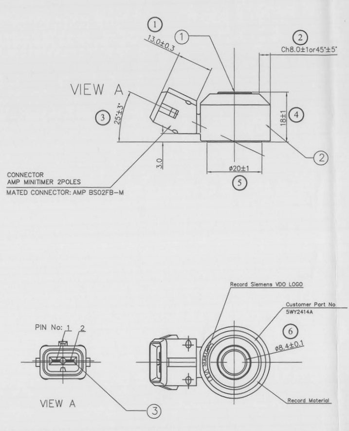
Figure 4
Introducing the impact sensor structure and physics:
Shock sensors prevent involuntary shocks as a result of sparking that occurs as a shock. Uncontrolled knocks are caused by high temperature combustion inside the cylinder. This phenomenon is caused by engine parts such as pistons, valves and cylinder head due to being affected by high stress.
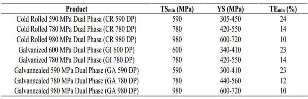
Figure 5: Wireless model
The shock sensor is placed in the engine block, so its shocks are caused by the shocks of the engine and can convert these shocks into an electrical signal. The vehicle’s control unit checks this signal and can control the engine, fuel injection and ignition until the impact limit is reached.
Due to the presence of this sensor, the engine can work closer to the fuel control limit to obtain a better combination and better fuel efficiency. Depending on their application, they may be made with a cable connector or without a connector. The connector may have 2 or 3 terminals, if they have a cable and a shield, the shield is connected to ground.
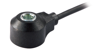
Figure 6: Impact sensor wired model
Impact sensors are distinguished by their sensitivity ( S ). Sensitivity is a rate between the potential created at the output terminal and the acceleration, depending on which one is exposed. This parameter is expressed in mV/g .
Non-resonant model shock sensors have this feature to keep the sensitivity constant throughout their range.
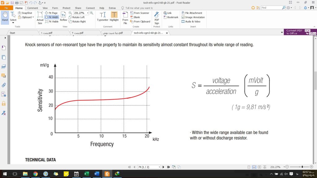
Figure 7: Sensitivity diagram (output voltage over input acceleration) according to the frequency of car engine vibrations.
Technical Specifications
• All impact sensors have been subjected to rigorous tests and must be 100% responsive.
• Working temperature -40 to 160 degrees
• Working range 1 to 20 kHz
• Sensitivity at 5 kHz
• Capacitance range: 800 to 1400 picofarad
• Main resonance: greater than 25 kHz
Function
Inside the shock sensor is a piezoelectric ring with electrical connection in each face and it is also reliably isolated from the body and the sliding mass. A piezoelectric sensor is a ceramic ring that is polarized by exposure to an external electric field, so it can create a potential difference when subjected to a compressive force.
The sliding mass is a metal ring that is reasonably calibrated to achieve the desired sensitivity when it comes into contact with the piezoelectric element of the sensor and is compressed by a spring washer and a nut that transmits motor vibrations to the sensitive element. The sensor transmits.
The metal part of the sensor (body) is responsible for transmitting vibrations from the engine body, before closing it, it is necessary to make sure that this area is clean and in an ideal condition, otherwise it is impossible to guarantee the correct operation of the sensor. not acceptable.
pic
Figure 8: Of internal parts and the arrangement of internal elements.
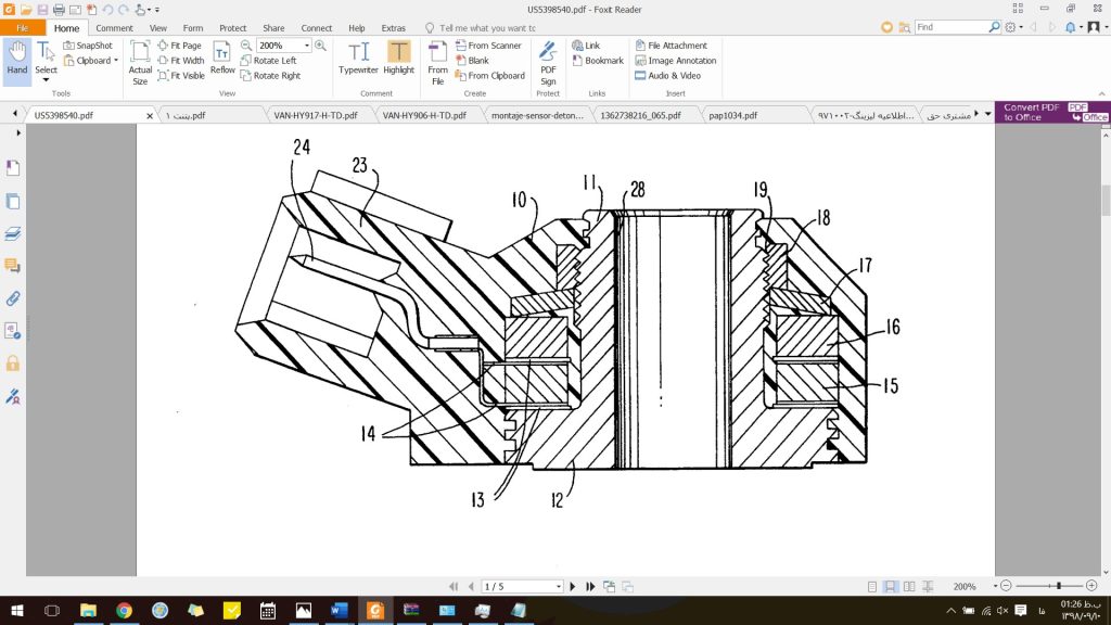
Figure 9: Structural view of the US Patent impact sensor.
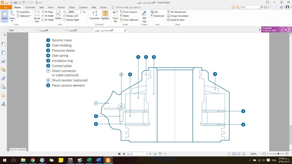
Figure 10: Internal structure of Bosch sensor
- Sliding mass (ceramic or metal weight)
- Outer body ==> injection
- Pressure lining ===> metal
- Annular spring ===> to transfer force to the sliding mass
- Insulation ring ==> prevent electrical connection, electrical insulation
with very low conductivity PET – R =15 GΩ - Connecting plate ===> Piezo output voltage transfer to the control center
- Direct or wired connection (optional)
- parallel resistor (optional)
- Piezoelectric Ceramic Element ===> Ringi Piezoelectric

Figure 11: Ceramic sample available on Alibaba website
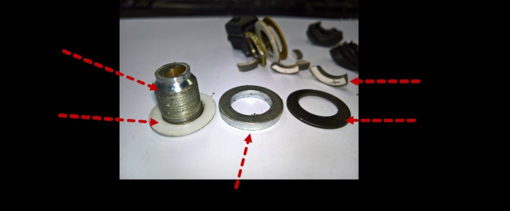
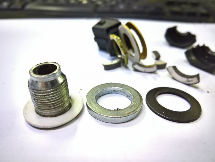
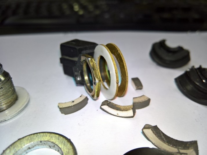
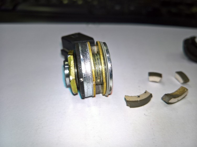
Figure 12: Of the disassembled sample
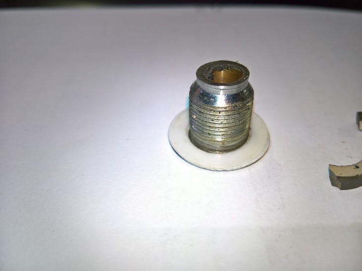
Figure 13: Of the central vertebra
Assembly steps
The construction of this sensor will be according to the following steps:
The piezoelectric core of this sensor can be obtained from Chinese suppliers. The electrical insulation part is made of PET, which is not 100% non-conductive and has a small amount of conductivity.
The resistance of this part is about 15 gigaherms, and the reason for that is the pyroelectric property of the piezo part, which creates a voltage in it at high temperature, and this The small electrical conductivity of the insulating piece can cause the discharge of this effect. This insulation is available in rolls on the Alibaba site with different conductivities.
The central screw can be ordered from domestic contractors, electrical connections and plate washers (disc spring) can also be ordered from domestic contractors as well as produced within the company. The sliding mass is made of … and can be produced in the company.
According to the pictures below, these parts are first assembled on the central screw and then transferred to the injection room and placed in the mold and injected.
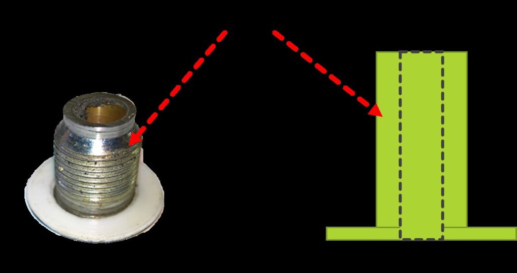
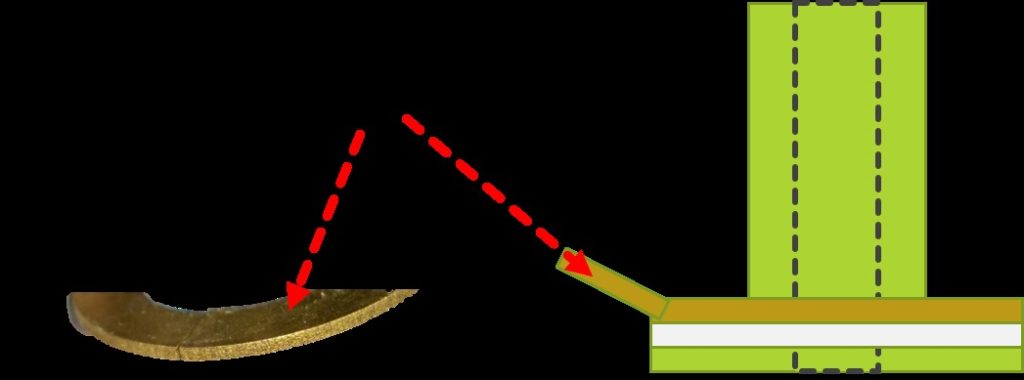
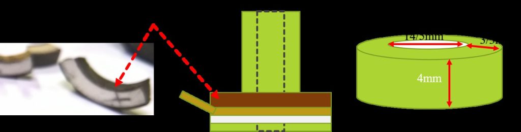
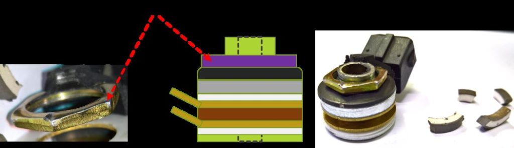
Figure 14
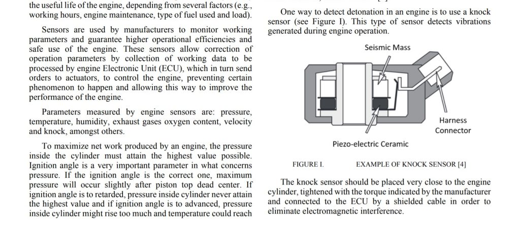
Figure 15
Specific tests of the impact sensor
- Capacitance of piezoelectric component
- The functional test of the sensor, which according to the figure… consists of a vibrator, on which a number of side measurement systems are installed, including voltage measurement to determine the sensitivity of the sensor with mV/g units at different operating frequencies Below is a schematic of this device.
Figure 16 is an example of an impact sensor test system that includes a vibrator that can be a piezo vibrator.
You can also put the LRC meter system on this device to check the capacitance of the sensor at different frequencies - One of the tests mentioned in some articles is the weight drop test. A body with a certain weight falling from a certain height on the surface of the sensor will have a certain output pattern
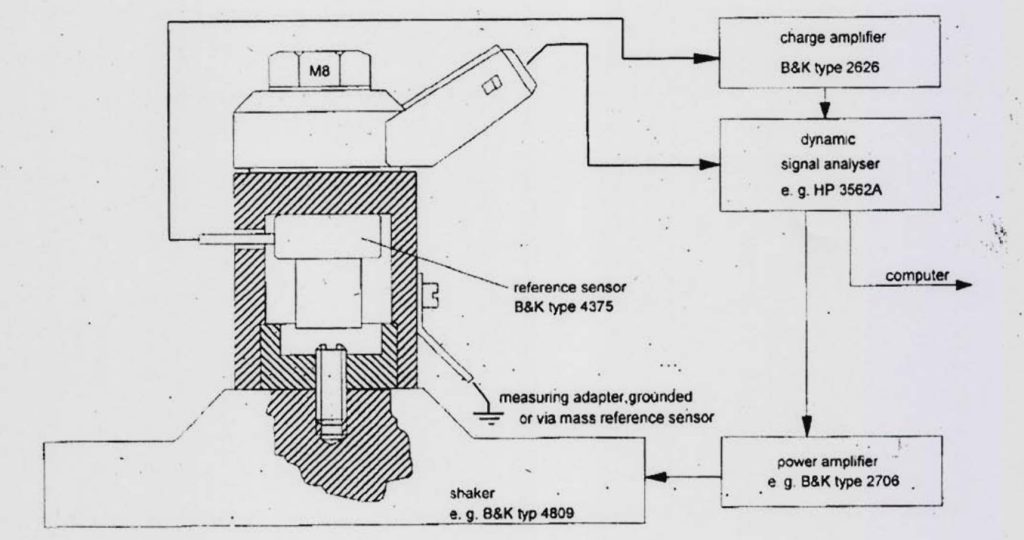
Figure 16
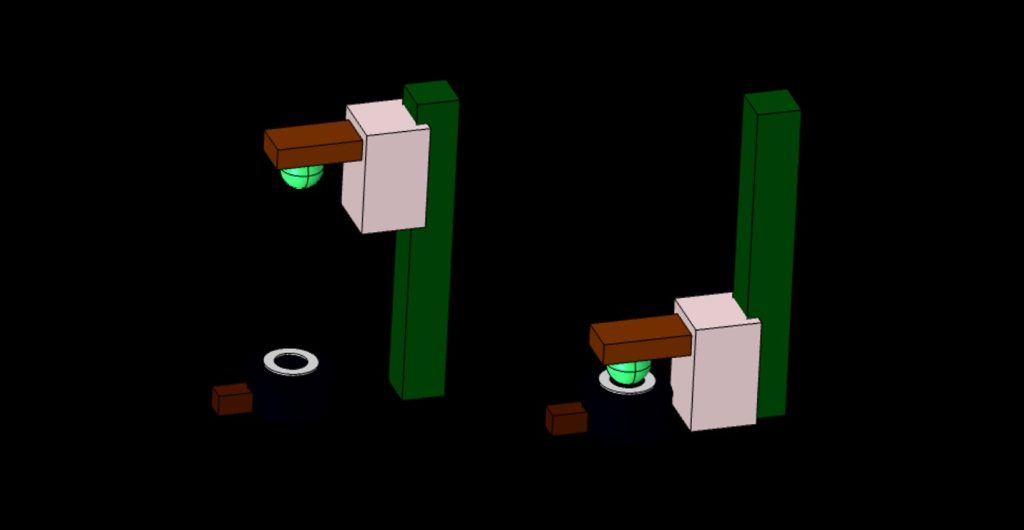
Figure 17: Proposed structure for testing the fall of a metal ball on the sensor
0 Comments