Hall effect sensors have gained increasing popularity due to their advantages in terms of size, economic feasibility, low power consumption, dynamic range, and integration with standard technologies. Various applications in automobiles and electronics require accurate current measurement to estimate electricity. In this section of Act Group, you will be introduced to the Hall sensor in the car and find out how the Hall sensor is used to measure the speed of the vehicle.
In this article, we review the definition of the main function and physical principles of the Hall effect sensor. The Hall sensor converts the changes in the magnetic field into an electrical signal, and its performance is justified according to the physical Hall effect.
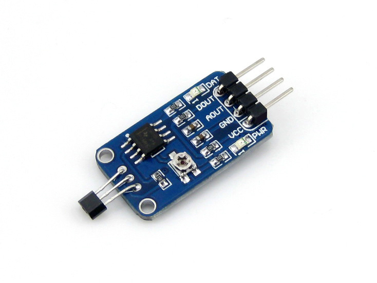
This chip includes a voltage regulator, a Hall sensor, a heat compensating circuit, a filter, an operational amplifier, and a Schmidt trigger.
The use of new technologies in the car leads to a significant increase in the electronic system of complex cars, which are also called embedded systems. Analysts estimate that 90% of innovations in the automotive industry are related to electronic systems.
In recent years, there have been new researches that improve vehicle performance in terms of four main factors: safety, comfort, energy saving, and gas emission reduction, led to the development of new products, many of which are Hall sensors.
Sensors are devices that are used in the engine to record signals. These sensors are generally expensive and fragile. The Hall effect sensor is used in the car to detect the position, the lifting window, the commutation of DC motors without the need for a brush, the distance and the speed of the cooling system.
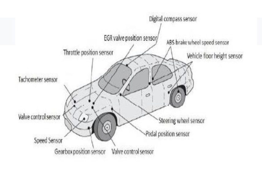
figure 1
In figure (1), we can refer to the Hall sensors used in the car. According to Xiao, the Hall effect sensor is a magnetic field sensor based on metal-oxide-semiconductor, Ketter Edwin Hall discovered the Hall effect in 1879.
According to Dr. Hall’s research, when the vertical magnetic field of a magnet is inserted into a thin rectangular side of gold that has an electric current, it causes a potential difference on the opposite side.
When there is no magnetic field and current, the distribution is uniform, no potential difference appears in it, the amount of voltage depends on the amount of current passing through the conductor and the magnetic flux density perpendicular to the rectangular plane.
In other words, the Hall effect sensor states that if a current passes through a conductive crystal in the direction perpendicular to the applied uniform magnetic field, the conductor will have a potential difference between the sides perpendicular to the direction of the current and the magnetic field.
In this case, a Lorentz force It is applied to the stream. This force causes a disturbance in the current distribution, which leads to a potential difference between the output terminals. This voltage is known as the Hall voltage. Figure (2) is related to the normal Hall effect .
pic
figure 2
where VH is the Hall voltage, RR is the effective Hall coefficient, I is the current from the sensor, t is the thickness of the sensor in millimeters, B is the magnetic flux density in Tesla. Hall effect is the result of the nature of the current passing through the conductor.
Current consists of the movement of a large number of charge carriers, usually electrons, holes, ions, or a combination of the three. The separation of charges creates an electric field that will oppose the continued migration of the charges, so a constant potential difference will exist as long as the current continues.
A very important feature of the Hall effect is that it differentiates between positive carriers moving in one direction and negative carriers moving in the other direction. Hall effect proves that electric current in metals is made by moving electrons and not protons.
Also, according to the Hall effect, in some materials, especially p- type semiconductors , the current is considered by the movement of electric holes. One of the important factors in the complexity of the Hall effect is that the holes that are moving to the left are actually the electrons that are moving to the right.
and carrier density are used. To calculate the electron transport properties, we need to describe the real space of electron behavior in the crystal. The use of substituted wave functions in real space allows us to assign a wave packet to the electron and examine its movement under the application of different fields.
A Hall effect sensor is a transducer whose work is based on the magnetic field, and in response to changes in the magnetic field, it shows the output voltage and produces an electric voltage due to the magnetic fields.
By applying relatively large magnetic fields, the output voltage is in the range of several microvolts. To improve the sensitivity of the sensor and get the desired output with the highest accuracy and minimum hysteresis error, an amplifier, voltage regulator and logic switching circuits should be used.
This sensor has wide applications and is also used in temperature, pressure and flow sensors. Among the features of these sensors, we can mention things such as solid state and long life as well as high speed and high frequency range.
Hall effect sensors are divided into two main types:
- linear or analog sensors, the output voltage of this type of sensor is taken directly from the output of the amplifier, which is proportional to the size of the applied external magnetic field.
- Hall effect sensors with digital output, these types of sensors have schmitt-There are triggers that are made based on the hysteresis loop and are connected to the amplifier.
Their output covers only two states:
– ON
– OFF
If the magnetic flux with a size greater than a reference value passes through the Hall element, the output will quickly change from the OFF state to the ON state.
Among the materials used to produce Hall sensors
- Gallium arsenide
- Indium arsenide
- Indium phosphide
- Graphene
Functional principles of the Hall effect sensor
A current flows continuously through this material. When the sensor is placed in a magnetic field, the magnetic flux lines exert a force on the semiconductor.
This force causes the charge carriers present in the semiconductor (i.e. electrons and holes) to be oriented to both sides of the blade. The output of the hall effect sensor can be digital or linear. In linear (analog) sensors, the sensor output is directly connected to an amplifier.
The signal is also taken from the output of the amplifier. This issue is shown in the figure below. The output voltage in this case is directly proportional to the magnetic field passing through the sensor. The output voltage is given as follows.
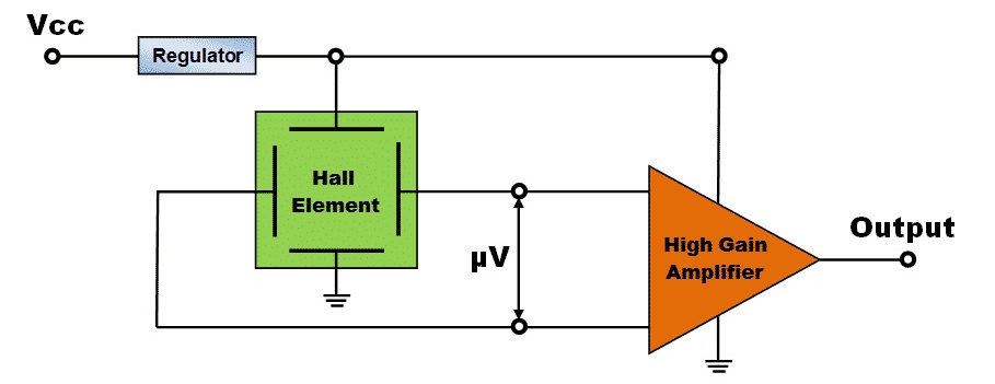
Figure 3: Hall sensor analog output
In the analog model, the output of the sensor changes according to the magnetic field around it, and it can be used to determine the intensity of the magnetic field or its distance. Figure (3) shows the analog output of the Hall sensor. On the other hand, Schmitt trigger is used in digital sensors.
A Schmitt trigger is a comparator circuit that uses positive feedback. It is also an active circuit that converts analog input signal to digital output signal. In this circuit, when the input voltage exceeds a certain threshold, the output voltage will be one volt. That means the key is in the ON position.
When the input voltage is lower than the threshold value, the output voltage of this circuit will be zero volts. That is, the key is in the OFF position. When this sensor is exposed to a magnetic field or the magnetic field is removed, no fluctuation is observed in the output circuit of the sensor due to the presence of the Schmitt trigger circuit.
Its digital type only has the ability to detect the presence or absence of a magnetic field around it (0 or 1), but in the analog model, the output of the sensor changes according to the magnetic field around it, and it can also be used to determine the intensity of the magnetic field or its distance. Recognized. Figure (4) shows the digital output of the Hall sensor.
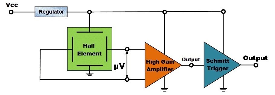
Figure 4: Hall sensor digital output
Hall effect sensor has two main digital types:
- Bipolar
- the other unipolar
Digital bipolar sensors need a positive magnetic field to activate and a negative magnetic field to deactivate. While monopolar sensors are activated by exposure to a magnetic field. If the sensor moves away from the magnetic field, the sensor will be disabled and no magnetic field is needed.
But unipolar sensors are activated by exposure to a magnetic field. If the magnetic field is moved away from the sensor, the sensor will be disabled. Switches that work with Hall effect sensors do not have the ability to switch to have a large electrical current output, because their capabilities are very limited.
The output current of these circuits is very small and around 10 to 20 milliamps. To have large electric currents at the output, an amplifier (an NPN transistor with an open collector) is used. This transistor works like an NPN switch.
Application of the Hall effect sensor in the car:
1. Windshield control
To determine the direction of the chassis, the direction of the glass position can be determined with the detector, and the Hall sensor affects and creates an output signal by controlling the lifting motor.
2. Brushless DC motor commutation
DC motors, the commutator converts the output of AC to DC and the Hall sensor reveals the position of the rotor by using the magnetism of the rotor and according to the position of the rotor, the connection of the windings moves the armature with the output of the motor and causes the conversion of AC to DC.
3. Car brake light switch
In the light switch, by pressing the brake pedal, the hall sensor causes a change in its magnetic field, and as a result, the sensor acts as a switch and activates the brake light, increasing the speed of operation and the life of this switch.
4. Electric motor speed
In engine speed, when a field is applied to the Hall sensor, a signal is output from it, and this signal is used to display the speed of the electric motor.
5. Measurement of electric current
A current is applied to the magnetic choke, this current changes the choke field and thus affects the sensor and the output of the sensor depends on the electric current.
Conclusion:
Today, there is a Hall sensor in the form of an IC and a package, which is produced for the purposes of Gonagoi.
The implementation of the Hall effect sensor, taking into account different conditions in the car, is in two ways, with a linear and digital sensor. The sensor with digital output is used in the glass of anti-trap elevators, DC motor commutation electric motor, brake light switch, electric motor speed, electric current measurement, etc.
0 Comments